Route Survey in Civil Engineering: A Comprehensive Guide
Introduction
In this article, we will read about the route survey process in civil engineering. This involves both field and office work needed to plan, design, and layout any long and narrow transportation facility, such as roads, railways, pipelines, and transmission lines.

Basic Concepts and Methods
Most of the basic survey concepts and methods are applicable to the route survey. Key tasks include measuring horizontal distances, heights, and angles, drawing maps, and preparing route profile and cross-section views.
Stages of Route Survey
Route survey operations usually involve three main stages: reconnaissance, preliminary, and location surveying.
Reconnaissance Survey
The reconnaissance survey is the first step. It involves examining a large area from one end of the proposed route to the other to select alternative routes. This step is crucial for selecting the most suitable path. For most projects, this involves using existing small-scale maps and aerial photographs.
Ground reconnaissance surveys can be used for small sections of existing routes. Sometimes, a complete topographic survey is conducted to prepare a detailed map. Aerial photos are often adjusted to form a strip mosaic to produce this map. In relatively flat areas, a planimetric map is usually sufficient at this stage.
Reconnaissance maps are used to compare different potential routes before performing a detailed survey or layout on the ground. Map scales range from 1 inch = 2000 feet (1:24,000) to 1 inch = 200 feet (1:2400).
Preliminary Survey
The preliminary survey can be carried out using ground surveying equipment or aerial photogrammetry in the office. Modern transit routes typically use low-altitude photogrammetric maps at a scale of 1 inch = 50 feet (1:600) with 2-foot (0.5-meter) contours.
These maps usually cover a width of about 1300 feet (400 meters), mainly along the alternate route corridor selected during reconnaissance. The primary purpose of this stage is to gather detailed information using photogrammetry, which allows for necessary computations for roadway design.
Location Survey
The main outcome of the preliminary survey is identifying the baseline or connecting traverse. This consists of a series of straight lines positioned at or near the midpoint of the final route, representing the horizontal alignment of the path without curves.
Distances along the route are marked as stations and pluses, starting from the beginning of the route. Baseline tangents and the angles at direction changes are carefully measured. Additional data is collected to show the profile of the traverse line.
The design of horizontal curves linking the tangential sections of the baseline depends on various factors, such as the topography and the maximum speed of vehicles using the route.
Final Design and Layout
After curve calculations and the preparation of field notes, the horizontal alignment of the route can be established on the ground during the location survey. This involves setting stakes along both the tangents and curves of the line (often along the offset line).
As the stations and pluses of the final centerline move along the curves and tangents, new stations must be calculated for points on the final alignment. During midpoint staking, topographic data is collected, and property nodes or right-of-way (ROW) boundaries are identified within the route.
Profile and cross-sectional data are obtained for the final design, the preparation of engineering drawings, and the estimation of earthwork quantities. The vertical alignment of the final grade line is set to equalize the volumes of excavation and embankment, ensuring a balanced cut and fill process.
Engineering Diagrams
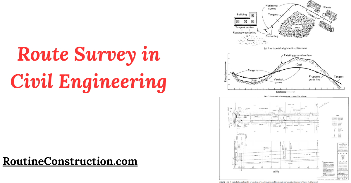
In engineering diagrams, the final horizontal alignment is displayed in the plan view, above the vertical alignment profile view. The plan view should include tangential bearings, angles of intersection, stations, and geometric data for each horizontal curve.
It should also show topographic data within and adjacent to ROW lines, as well as any existing structures affected by the project. The profile view should depict the existing ground surface, the proposed route grade line, the slopes of all tangent sections, vertical curve data, and other relevant information.
Conclusion
The route survey is a comprehensive process that ensures the successful planning, design, and layout of transportation facilities. By following the stages of reconnaissance, preliminary, and location surveying, and utilizing modern tools like aerial photogrammetry, engineers can create accurate and efficient route designs.
This guide provides a detailed overview of the essential steps and considerations involved in a route survey, highlighting its importance in civil engineering projects.
