Introduction to Geodimeter
The Geodimeter, a groundbreaking surveying instrument based on the propagation of modulated light waves, was developed by E. Bergestrand of the Swedish Geographical Survey in collaboration with the manufacturer, M/s AGA of Sweden. Among the various models they produced, the Geodimeter Model 2-A is specifically designed for nighttime observations, while Model 4 is suitable for limited daytime use.
This article provides a comprehensive

Components and Working of Geodimeter
Schematic Diagram and Physical Appearance
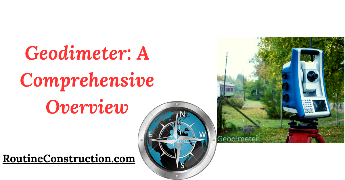
The schematic diagram of the Geodimeter illustrates its intricate design. The photograph below shows the front panel of the Model-4 Geodimeter mounted on a tripod. The main instrument is positioned at one end of the line to be measured, with its back facing the other end. A reflector, consisting of either a spherical mirror or a reflex prism system, is placed at the opposite end of the line.
Light Propagation and Modulation
The Geodimeter uses an incandescent lamp to produce light. This light:
- Is focused using an achromatic condenser and passed through a Kerr cell. The Kerr cell contains two closely spaced conducting plates with nitrobenzene between them. When high voltage is applied, the light is split into two parts, each traveling at different velocities.
- Two Nicol prisms are placed on either side of the Kerr cell. The first prism polarizes the light plane, and the Kerr cell splits it into two beams with a phase difference. Upon leaving the Kerr cell, the light is recombined, resulting in an elliptically polarized beam.
Light Reflection and Reception
The diverging light from the second polarizer is focused into a parallel beam by the transmitter objective and reflected off a minor lens onto a large spherical concave mirror. At the other end of the measured line, a reflex prism system or spherical mirror reflects the light back to the Geodimeter.
The receiver system of the Geodimeter includes a spherical concave mirror, a mirror lens, and a receiver objective. The variable intensity light, after reflection, hits the phototube’s cathode. In the phototube, light photons cause primary electrons to travel to the first dynode, where secondary emission occurs.
This process repeats through eight dynodes, amplifying the final electron current at the anode by hundreds of thousands of times.
Sensitivity and Delay Adjustment
The sensitivity of the phototube is adjusted by applying high-frequency Kerr cell voltage between the cathode and the first dynode. Low-frequency vibrations are filtered out using electrical chokes and condensers. An adjustable electrical delay unit manages the passage of modulating voltage through the instrument.
The difference in currents during positive and negative bias periods is measured on a null indicator, a sensitive D.C. moving coil micro-ammeter.
Phase Adjustment and Distance Measurement
To equalize the negative and positive current intensities (achieving a null point), the phase of the high-frequency voltage from the Kerr cell must be adjusted ± 90° concerning the voltage generated by light at the cathode. The focused light beam from the Geodimeter at one end to the reflector at the other end of the line reflects back to the photomultiplier.
Variations in the intensity of this reflected light cause current variations in the photomultiplier, already varied by the direct signal from the crystal-controlled oscillator. The phase difference between the pulses received by the cell measures the distance between the Geodimeter and the reflector.
Frequency and Phase Settings
Model-2A of the Geodimeter offers three frequencies, while Model-4 provides four frequencies. The phase position indicator offers four phase positions, with phase changes indicating the reversal of Kerr cell terminal polarity. Fine and coarse delay switches control the electrical delay settings between the Kerr cell and the photomultiplier. The instrument is powered by a mobile gasoline generator.
Performance and Specifications
Model-4 Geodimeter Specifications
Night Range: 15 meters to 15 km
Daylight Range: 15 to 800 meters
Accuracy: ± 10 mm ± five millionths of the distance
Weight: Approximately 36 kg (excluding the generator)
Conclusion
The Geodimeter, with its advanced light propagation and modulation techniques, has significantly enhanced surveying accuracy and efficiency. Its ability to measure distances with high precision, both at night and in daylight, makes it an invaluable tool in the field of surveying.
